
 zprávy
Proč je nutné impedanční přizpůsobení
Odhadovaná doba čtení: 15 minut
Největší rozdíl mezi rádiová frekvence (RF) a hardware spočívá v impedančním přizpůsobení a důvodem impedančního přizpůsobení je přenos elektromagnetických polí. Jak všichni víme, elektromagnetické pole je interakce mezi elektrickým a magnetickým polem. Ztráta v přenosovém médiu nastává, protože elektrické pole způsobuje oscilace ve svém účinku na elektrony. Čím vyšší je frekvence , čím více cyklů elektromagnetických vln je v přenosovém vedení stejné délky a tím vyšší je frekvence změn proudu. V důsledku toho se zvyšují tepelné ztráty generované oscilacemi, což vede k větším ztrátám v přenosovém vedení.
Při nízkých frekvencích, protože vlnová délka je mnohem delší než přenosové vedení, zůstávají napětí a proud na přenosovém vedení v obvodu téměř nezměněny, takže ztráty v přenosovém vedení jsou velmi malé.
Pokud dojde během výstupu vlny k odrazu, superpozice odražené vlny s původní vstupní vlnou může vést ke snížení kvality signálu a také ke snížení účinnosti... přenos signálu .
Ať už pracujete na hardwaru nebo VF systémy , cílem je dosáhnout lepších výsledků přenos signálu a nikdo nechce, aby se v obvodu ztrácela energie.
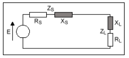
Když je odpor zátěže roven vnitřnímu odporu zdroje signálu, zátěž může dosáhnout maximálního výstupního výkonu. Tomu se často říká impedanční přizpůsobení.
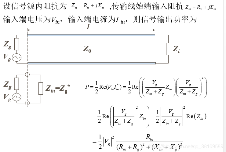
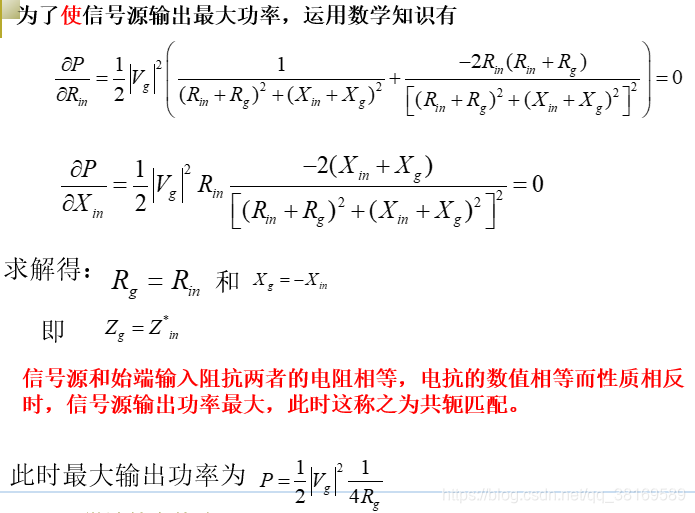
Je důležité si uvědomit, že konjugované přizpůsobení slouží k maximálnímu přenosu výkonu.
Podle vzorce pro koeficient odrazu napětí ( \Gamma = \frac{Z_L - Z_0}{Z_L + Z_0} \) se \Gamma v tomto okamžiku nerovná 0, což znamená, že dochází k odrazu napětí.
Pro bezzkreslené přizpůsobení jsou impedance zcela stejné, takže nedochází k odrazu napětí. V tomto případě však není výkon zátěže maximalizován.
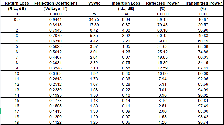
Ztráta odrazu (RL) = \( -20\log|\Gamma| \)
Poměr stojatých vln napětí (VSWR) = \( \frac{1 + |\Gamma|}{1 - |\Gamma|} \)
Vztah mezi poměrem stojatých vln a
účinnost přenosu
je uvedeno v tabulce níže:
Impedanční přizpůsobení zahrnuje poměrně zdlouhavý proces výpočtu. Naštěstí máme Smithův diagram, základní nástroj pro impedanční přizpůsobení. Smithův diagram je diagram složený z mnoha protínajících se kružnic. Při správném použití nám umožňuje získat impedanci přizpůsobení zdánlivě složitého systému bez jakýchkoli výpočtů. Jediné, co musíme udělat, je číst a sledovat data podél kruhových čar.
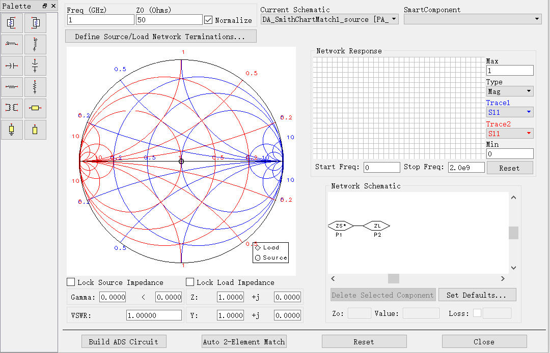
## Metoda Smithova grafu
1. Po zapojení sériové kondenzátorové součástky se bod impedance pohybuje proti směru hodinových ručiček podél kružnice s konstantním odporem, na které se nachází.
2. Po připojení součástky s paralelním kondenzátorem se bod impedance pohybuje ve směru hodinových ručiček podél kružnice s konstantní vodivostí, na které se nachází.
3. Po zapojení sériové cívky se bod impedance pohybuje ve směru hodinových ručiček podél kružnice s konstantním odporem, na které se nachází.
4. Po připojení lateralizované indukční součástky se bod impedance pohybuje proti směru hodinových ručiček podél kružnice s konstantní vodivostí, na které se nachází.
5. Po připojení otevřeného bočního vodiče se bod impedance pohybuje ve směru hodinových ručiček podél kružnice konstantní vodivosti, na které se nachází.
6. Po připojení zkratovací součástky se bod impedance pohybuje proti směru hodinových ručiček podél kružnice konstantní vodivosti, na které se nachází.
7. Po připojení komponenty sériového přenosového vedení se bod impedance pohybuje ve směru hodinových ručiček podél kružnice konstantní stojaté vlny.